The Behringer BDI21 is the well-known cheap clone of the Tech21 SansAmp BDDI V1, but what's less known is that it's a clone of the early V1, which does not have any explicit overdrive circuitry. Behringer did an almost exact clone, but their hardware changes don't have the same behaviour as the original. Fortunately, we can fix the differences and add some useful changes of our own, without having to remove or replace any of the tiny SMD components.
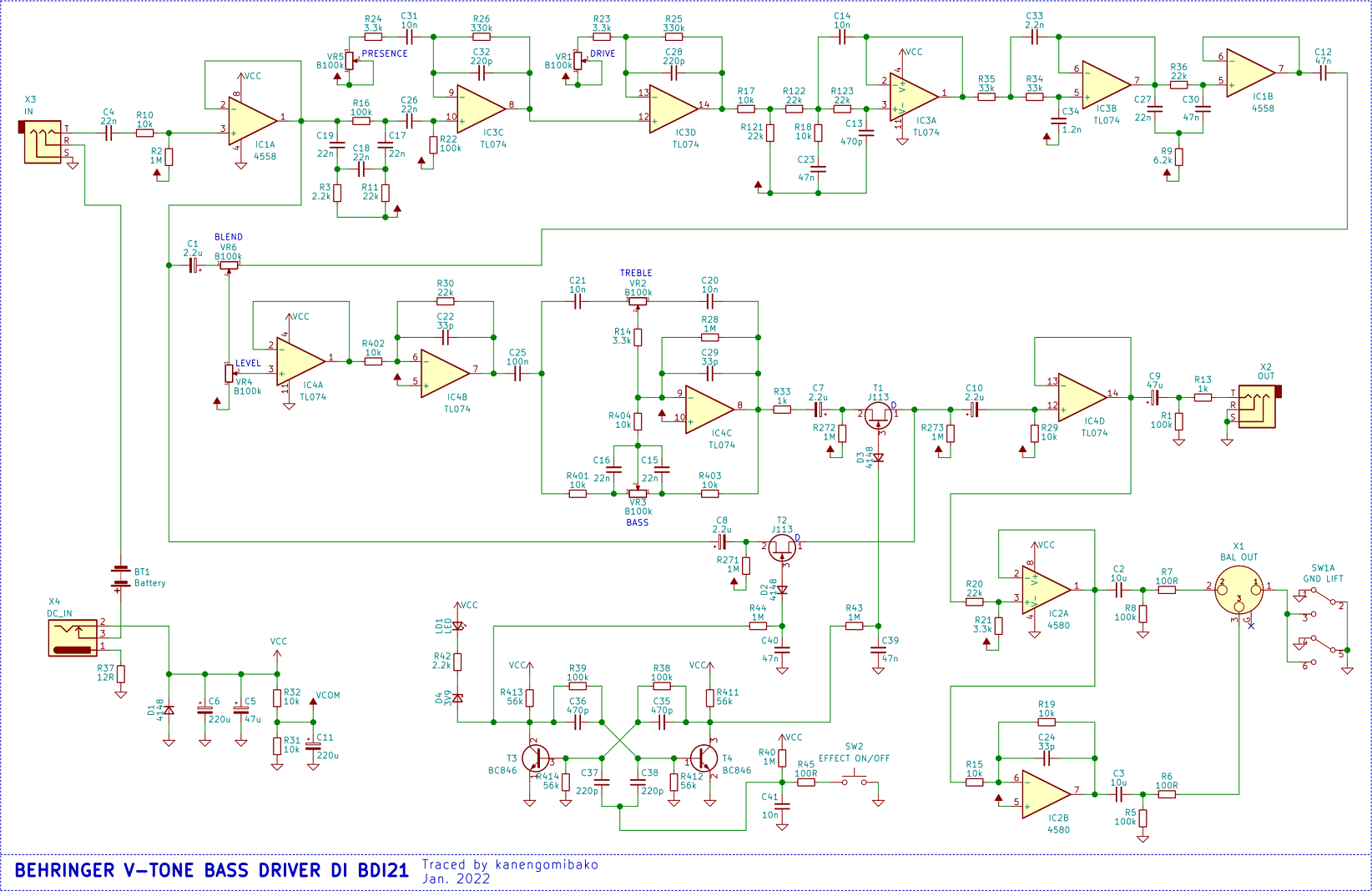
For reference, here is the schematic traced by kanengomibako, originally from Combustible Trash Can (in Japanese). For comparison, kanengomibako also traced out the schematics for the original SansAmp BDDI V1 and V2.
Note that in the BDI21, the SMD components are glued down prior to soldering, which means replacing them would be difficult, but on the other hand, soldering extra hardware to them is then easier since you won't dislodge a component accidentally. Also, each component is clearly labelled on the PCB with the schematic part number and its value. Watch out for any solder bridge shorts to the leads of the through-hole capacitors (my unit arrived with such a short).
Knobs and major sub-circuits in order from input to output:
The plastic case is quite solid, but doesn't shield the electronics from ambient electrical noise. Shielding the case makes the pedal a lot quieter. I pulled out all the knobs (they are friction fit) and unscrewed the board, then painted the inside of the case with two coats of good carbon shielding paint (from Solo Music Gear) to get to 30 Ohms/sq, making sure to cover the lip where the back-plate sits (and to NOT cover the LED bezel), and cleaned up the steel back-plate with a fine Scotch-Brite pad to ensure a good electrical contact with the carbon paint.
Shielding a plastic case is critical if you are adding metal switches for modifications: the wires to the switches and the floating switch bodies will all act like antennas inside the unshielded plastic case. I was getting RFI to the point of saturating the op amps in the main overdrive path, causing the pedal to cut out. An initial quick solution was to solder a ground wire to the switch bodies and twist that wire and the signal switch wires together into a bundle to reduce the loop area, but shielding the case is easier and better, and it automatically grounds the switch bodies which are rather difficult to solder to.
To reduce any RF EMI entering the pedal, I soldered 100pF capacitors directly across the power terminals and across the input and output tip and sleeve terminals.
I considered adding 1uF decoupling caps across each op-amp chip, but there is not enough clearance between the board and back-plate. However, I have not noticed any instability in the op-amps, and Behringer did make an effort at placing the electrolytic power filter caps on ground planes near each op-amp chip. They do indeed reduce noise from the power supply, which is also far above any frequency the BDI21 will let pass through its audio filters.
This is the main problem with the BDI21: Resistors R32 and R31 form a voltage divider to generate a 4.5V signal bias voltage (VCOM) from the 9V supply (VCC), which makes the virtual signal ground sit only 0.5V above the bottom of the common-mode voltage (Vcm) range of the TL074 op-amp, which is (V-)+4V to V+, or in our specific case, 4V to 9V (approximately). By comparison, the Vcm range of the TLC2264 op-amp used in the original SansAmp is nearly symmetric around the mid-supply point, and spans almost the entire range from V- to V+, so a 4.5V bias was perfect.
We want to avoid inputs outside the Vcm range as the op-amp behaviour can be unexpected. For example, while the OPA141 op-amp appears to work just fine with rail-to-rail inputs outside its Vcm range, there is a narrow input level band where the output will oscillate at high frequency. This is not in the datasheet, because you are not supposed to go outside the Vcm range. The TL074 has a similar problem where I'll hear some odd noises at higher Presence/Drive gains, and then outright phase inversions (nasty full-swing spikes to V+) as the input reaches near V- (almost 0V, in this design).
To keep the inputs to the TL074s in the linear Vcm range, we need to bring the bias voltage (VCOM) up to about 6.8V, placing it in the middle of the 4V to 9V Vcm range. It's not 6.5V because the current-limiting (?) R37 at the power socket raises ground to 0.3V (implying 25mA of current, which is what's expected). The other op-amps in the BDI21 (4580 and 4558) have larger Vcm ranges, so they are fine.
To adjust the bias voltage upwards, we need about 6.3k in parallel with R32. I took a 5k multi-turn trimpot, added 1k resistors to each leg, and soldered that across R32 using a couple inches of wire as there is no clearance between the board and back-plate. I then adjusted VCOM until it was 6.8V.
A narrow mid scoop around 800 Hz sounds really good on electric bass, but sometimes I don't want it if I'm driving another amp/cab modeler with its own EQ curve. Add a switch across R16, right after the input buffer, to bypass the 750 Hz notch circuit. This also removes that notch filter's insertion loss, which increases the signal level at that point by as much as 10 dB. You will have to re-adjust all other setting afterwards.
Even with the notch filter disabled, there is still a mild mid scoop due to the configuration of the cab sim filters after the Drive stage, but that scoop is shallow (as little as -3dB, depending on Bass/Treble knobs) and very broad, roughly spanning about 200 Hz to 2 kHz, with humps at about 100 and 2.5 kHz which can be individually raised/lowered by the Bass/Treble knobs. Not a bad bass cab sim curve, I think!
R22 and C26 form a 72 Hz HPF, which I suspect is part of the cabinet simulation, as very few actual bass cabinets can reproduce much below 50 Hz at best. However, since I am adding overdrive and play a 5-string tuned to B-Standard (32 Hz), I want those lowest frequencies to be present so the harmonically-related overtones generated by the overdrive are based on the fundamentals and first few harmonics of the B and E strings, which will improve the perception of those lowest frequencies when played through speakers or headphones which cannot reproduce them.
On the other hand, I don't want to mess with the AC coupling across stages, so let's instead lower the HPF frequency to 17.7 Hz by soldering a 68nF capacitor across C26, for a total of 90nF, which reduces the attenuation at 32 Hz to about -1.2dB.
The Presence stage is meant to emphasize only the upper harmonics of the notes you are playing, which will improve their perceived brightness. Anectodally, I read the SansAmp was developed and tested with a vintage Precision bass, so a Presence stage made perfect sense. However, with a modern active bass and very bright stainless steel strings and full-range studio headphones, all Presence does is amplify string noise and electronic hiss. Even turned all the way down, it still acts a bit like a HPF by emphasizing only frequencies above 154 Hz, so that also robs us of some low end we want to hear and feed to the overdrive.
Let's instead lower the range of Presence to span 14 Hz to 438 Hz, from lowest to highest gain, by soldering a 100nF capacitor across C31. By also adding a switch across C31 we can bypass the capacitors altogether, which converts Presence into a Clean Boost stage. Either mode then feeds into the Drive section, which modifies its overdrive behaviour.
The modified Presence control works the same as before, increasing both gain and minimum affected frequencies as you turn the knob. The effect begins with a mild boost starting at the very lowest end (below 100 Hz) and ends with a very strong boost starting at the low mids, which gives a lot of, well, presence and a pleasant tone that contrasts the built-in high mid scoop.
I think the original early SansAmp implemented overdrive by clipping the op-amp itself, and partially relied on the TLC2264's limited gain-bandwidth and slew rate to attenuate the highest generated overtones. In the BDI21, the feedback capacitors (C32 and C28) are larger to accomplish the same goal. We can't clip the TL074 the same way due to the smaller and very asymmetric common-mode range (Vcm). We also want a softer clipping option than the raw op-amp clipping. In fact, several circuit features line-up to give us clipping so soft, it can behave like plain compression!
Add two switches, each in series with a germanium 1N34A diode, each backwards from the other, across R25 to implement the usual Tube Screamer style soft-clipping topology with one major difference: the location of the gain adjustment (VR1) is not across the diodes but on the other leg of the VR1/R23/R25 voltage divider. You can also add a pair of reverse-parallel 1N4148 silicon diodes in series with the above to raise the voltage at which clipping will begin, giving a louder overall signal.
When a feedback diode clips, it reduces the op-amp gain towards unity, so the output approximately matches the input. Normally, the overdrive gain is so high the clipped part of the signal is proportionately flat compared to the scale (and slope!) of the amplified, unclipped output. By instead feeding in a pre-amplified signal, thus reducing the amount of overdrive gain needed to clip, we end up with a softer clipping behaviour. By using germanium diodes we get an even softer clipping behaviour, which means fewer upper harmonics when driven hard.
Furthermore, given the location of the Drive potentiometer (VR1), a lower gain means a higher total resistance in that leg of the voltage divider formed by R25/R23/VR1, so that means much less current flows through the diodes when clipping, mere microamps, which operates the diodes in their very non-linear region near the start of conduction, giving a more interesting distortion and a very soft start to clipping.
In parallel with all that, solder two green LEDs, also each backwards from the other. Green LEDs typically have a forward voltage drop of about 2V, which in combination with the corrected bias voltage, limits the output of the Drive stage to within the TL074 common mode range. This is particularly important to limit large negative output signals. Positive output signals will clip either at the op-amp positive output swing limit (which is within the Vcm range), or at the green LED forward voltage.
By closing either diode switch, you can select positive or negative asymmetric overdrive, leaving the other half of the waveform unclipped and effectively blending in some original signal. The polarity does make a significant difference to sound, because guitar signals are not symmetrical waveforms. You can also do asymmetric overdrive by closing one switch and turning up Drive until a green LED act as the other clipping diode.
Closing both switches creates the more common symmetric overdrive. You can also turn off both switches and turn up the gain until you clip against both green LEDs.
You can also alter the overdrive behaviour by instead using the Presence stage as a clean or mid boost into the overdrive, then using a lower overdrive gain.
This very soft overdrive can act as a very basic compressor: Keep Drive and Presence at minimum and turn on both diode switches. The resulting clipping on the very current-limited germanium diodes is so soft there is none of the usual harsh overdrive sound, and the output signal is pleasantly compressed. You can select for more overdrive and less compression by only using one of the diodes, or for the same compression with more overdrive by turning up Drive. You can turn up Presence to have a mid-boost and not affect the compression too much.
To illustrate why: If we take a steady instrument-level input signal from a guitar to be 50 mV peak, and the insertion loss of the 750 Hz notch filter to be -10 dB (x0.316), then we end up with a 16 mV peak signal into the Presence stage. The minimum gain of the Presence and Drive stages is about 4x, so with both Presence and Drive at minimum, the diminished input signal is amplified back up to 253 mV peak after the Drive stage, which is the approximate forward voltage of the 1N34A germanium diodes. However, since the Drive gain is at minimum, there is a 103 KOhm resistance in series with the diodes, limiting their current to less than 2.5 uA, so their dynamic impedance remains high, and drops slowly as the input signal rises, resulting in compression more than overdrive.
To offset the lowered volume when compressing, let's add 6db (x2) of gain to the signal path: solder a 10 kOhm resistor across R402. This is best done by placing the new resistor across pins 1 and 6 of IC4, as R4 is a minuscule package of multiple resistors too difficult to solder to. Control the gain with Level, as usual. The new gain also works with Blend at minimum, bypassing all but the Bass/Treble EQ, so this is another way to get some clean boost.
In the link above, kanengomibako noticed that C25 (just left of centre) leading into the output tonestack is reduced from 2.2uF in the SansAmp to 0.1uF in the BDI21. The reason for this change is unknown, and kanengomibako shows through simulation that it turns the shelving Bass control into a peaking control with less range. It also causes the Treble control to attenuate the low end. We can restore the original behaviour by soldering two 1uF capacitors across C25, which gets us back to 2.1uF total. This change also restores the expected "flat at noon" behaviour: with Blend at minimum, there is barely any noticeable difference in tone betwen engaged and bypassed.
NOTE:The cab sim filters were likely tuned to account for the initial HPF and the compounding HPF effect of the Presence circuit, so after these modifications, the low end will be much louder. Turn down the Bass knob to compensate if needed.
That's it. Have fun.