Replacing a Germanium Diode with a Silicon Diode
Charles Eric LaForest, PhD., GateForge Consulting, Ltd.
These are quick notes and experiments to flesh out an idea I stumbled upon.
It's a detailed draft, not a full treatment, of a more detailed design approach
with diodes for distortion and saturation.
You can try out these circuits (including the bias supply and input buffer) in the interactive CircuitJS1 simulator: germanium_replacement.cjs1.
Germanium diodes create a pleasant, softer distortion than modern silicon
diodes, but are no longer in production, are getting hard to obtain, and there
have been cases of Schottky diodes being passed off as germanium diodes, both
deliberately and accidentally.
Both Schottky and germanium diodes have similar lower forward voltages at
currents in the range of milliamperes, but Schottky diodes are much leakier
when reverse-biased, and so do not behave the same when used to clip signals.
Also, approximating diodes as one-way switches with a relatively constant
forward voltage drop misses out on their best feature for creating pleasing
distortion: the non-linear (exponential) relationship of the forward current
to the forward voltage.
Both germanium and silicon diodes are modeled by the same Shockley diode
equation, so we should be able to find a different operating point for a
given circuit so that a silicon diode will give us the same behaviour as a
germanium diode.
I'm not going to try and analytically derive the desired behaviour from the
system formed from the Shockley equation along with the voltage divider and
parallel resistance equations. Instead, it's much easier to experiment directly
in an interactive simulator and explain qualitatively what happens and why.
That will suffice for you to alter these examples to get the specific behaviour
you want.
Reference Circuit

Let's assume a common signal IN, already pre-amplified and biased, which we
use to drive different circuits. The first one is the reference: a plain
non-inverting amplifier with a gain of 2. The op amp output feeds a voltage
divider formed by the two 330k resistors, with the "top" resistor driven by the
op amp, and the "bottom" resistor going to the virtual ground (Vbias). We use
the de-biased output (OUT_REF) as the scale reference so all other circuit
outputs are comparable.
From Clean Boost to TubeScreamer
We will add diodes to the reference circuit, from the op amp output to its
inverting input, to construct a conventional TubeScreamer-style soft-clipping
circuit, where the "top" and "bottom resistors each control a different aspect
of the resulting distortion.
The "top" resistor is in parallel with the dynamic resistance of whichever
diode is forward-biased at a given moment. The ratio of these parallel
resistances determines what fraction of the total current goes through the
diode, and thus how much the non-linearity of the diode affects the total
current.
The "bottom" resistor is in series with the above parallel resistance, and
thus both limits the current through the diode and converts that current into
the feedback voltage controlling the op amp. A larger resistance multiplies
more the changes in current through the diode, but also lowers the current.
By choosing the right resistance value, we can tune the non-linearity of
the diode.
Tuning Silicon Clipping to Match Germanium Clipping
We will make two soft-clipping variations of the reference circuit: one with
1N34A germanium diodes (OUT_IN1N34A), and one with 1N4148 silicon diodes
(OUT_1N4148). These two circuits will of course have different clipping
behaviour.
To make the silicon diode circuit clip identically to the germanium diode
, we take the same silicon soft-clipping circuit, but
reduce both "top" and "bottom" resistance by 100x from 330k to 3.3k (OUT_1N4148_SOFT). This
dual reduction leaves the maximum gain unchanged (2) and accounts for the lower
dynamic resistance of the silicon diode.
(Addendum: later experiments showed a 70.2x reduction (4.7k resistors) gives an even closer match.)
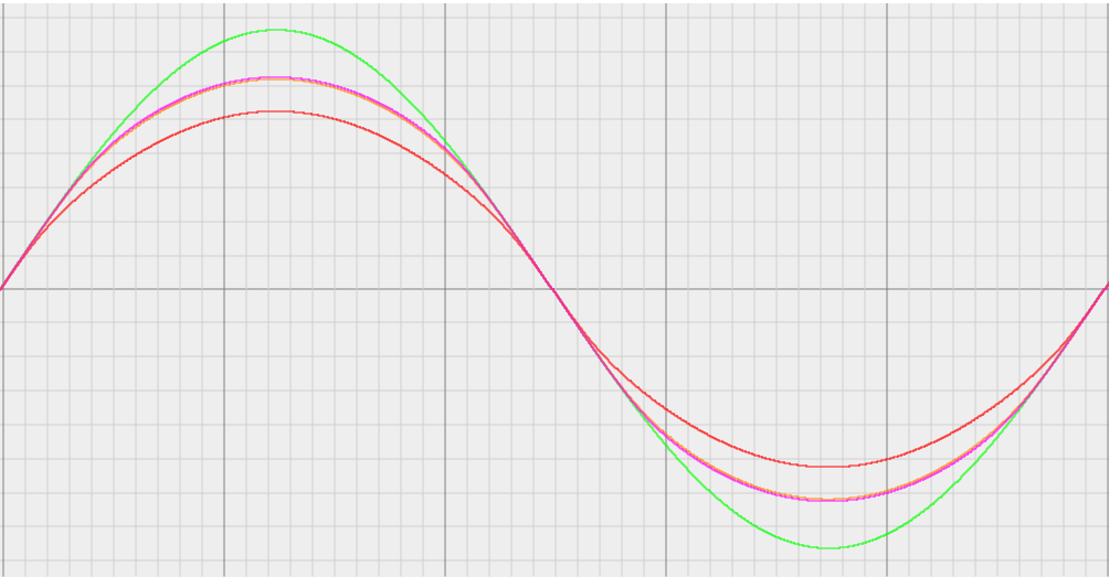
The waveform on the left compares the four circuits. The largest, green
trace is the undistorted reference output (OUT_REF), which reaches 1.53Vp,
implying the input signal (IN) reaches 765mVp.
The smallest, red trace is the silicon soft-clipping output (OUT_1N4148),
which has the most clipping since the 1N4148 diode has the least dynamic
resistance, thus lowering the overall gain as part of the "top" parallel
voltage divider resistance. We know this curve is clipping and not just a lower
gain, because the slope near the zero crossing (where the diodes conduct very,
very little) is the same as the reference.
The two middle, nearly overlapping purple and orange traces are the
germanium (OUT_1N34A) and germanium-replacement silicon (OUT_1N4148_SOFT)
soft-clipping circuits. Although I show only one operating point, the two circuits
remain matched regardless of the input voltage (IN) or the circuit gain. Any
proportionate change (e.g.: halving, tripling, etc...) to the "top" and/or
"bottom" resistors of both the germanium and germanium-replacement silicon
circuits results in the same matching waveforms.
Adjusting Distortion and Saturation
Given a constant amplitude input, changing the "top" or "bottom"
resistances has different effects on the overall distortion:
Increasing the "bottom" resistance decreases the current through the
forward-biased diode, which lowers its forward voltage, and vice-versa when
decreasing the "bottom" resistance. This change affects the signal level at
which clipping begins, where the gain smoothly transitions from the clean
undistorted gain set by the "top" and "bottom" resistors, to the non-linear,
distorting, reduced gain from the diode dynamic resistance in parallel
with the "top" resistor.
Decreasing the "top" resistance lowers both the clean and distorting
gains and thus also lowers the peak voltage, which means less of the waveform
is distorted by clipping, as set by the "bottom" resistor.
Increasing the "top" resistance increases mainly the clean gain, giving a
sharper slope to the unclipped signal below the level set by the "bottom"
resistor, but without changing the peak voltage significantly since the
"bottom" resistor sets the diode current.
Varying both "top" and "bottom" resistors together, while keeping the gain
constant, changes the amount of saturation (decrease in gain past a certain
amplitude, as in tube amplification or tape recording or transformer
saturation, etc....) without adding higher overtones from conventional
gain-based distortion as when increasing the "top" resistance only.
By selecting a mild gain and the right input level and "bottom" resistance,
this saturation behaves like a mild compressor (e.g.: 2:1 or so) with an
immediate attack and release, which is perfect for adding pleasant overtones to
the lower notes of a bass guitar while controlling their usually higher
amplitude. It also limits sharp attacks from tapping, slapping, and picking.
fpgacpu.ca


